Lab Exercise #3: Spatial Interpolation: Inverse Distance Weighting and Kriging of Several Datasets including Ozone concentration.
Background
In this lab you
will use Arc/INFO (or ArcView if you can find the Avenue scripts to do it) to
perform some spatial interpolations on various datasets. You will use two kinds
of spatial interpolation: Inverse Distance Weighting (IDW) and Kriging. To get
an idea of how IDW and Kriging works simply read the info in Arc/INFO’s on-line
help system: Arc Doc. Both IDW and Kriging are functions in Arc’s Grid module
that produce an interpolated surface from a set of point measurements. For
example, let’s say you have a single rainfall measure at the centroid of each
of the 48 conterminous United States; the IDW and Kriging functions can
‘estimate’ the rainfall anywhere in the conterminous U.S. and produce a grid of
those estimates. Using 50 points for the whole conterminous
Outline of your tasks/objectives
1) Do a single IDW calculation by hand and describe how the Grid function IDW does a whole lot more.
2)
Your second task will be to simply take a point
coverage of ozone measurements made throughout the
3)
One problem with the IDW and Kriging exercises in task #2 is that you can’t
really assess how good or bad your interpolations were. So in this third task
you will take a complete grid of three datasets (a DEM of the
4)
Build a ‘detrended’ kriged estimate of ozone in Great Smoky NP and compare to
Specific
Instructions for Tasks 1-4
Task #1: Inverse Distance Weighting by hand
The table below represents x and y coordinates of something called ‘Value’. Estimate the value of the fourth record (indicated by a ‘?’) using inverse distance weighting. Draw a crude scatter plot of the data in the table to the right of the table.
|
X coord |
Y coord |
Value |
|
1 |
3 |
11 |
|
3 |
5 |
7 |
|
2 |
7 |
3 |
|
3 |
3 |
? |
|
7 |
4 |
9 |
Now, enter this table into Excel or some text editor and read it in as an ‘event theme’ to ArcView. Convert that shapefile to an Arc/INFO point coverage and do an IDW on that point coverage. How did the output of Grid’s IDW command differ from your simple hand calculation? Explain.
Task #2: Kriging and IDWing
without a ‘truth’ or reference grid
If you look at the Point Attribute table for the point coverage ‘usozonesites’ (usozonesites.pat) you will find that there are numerous attributes. We will work with the attribute: ‘O3apr2oct_’ (don’t forget the underscore ‘_‘at the end). First we will create an interpolated grid of the ‘O3apr2oct_’ values using the Inverse Distance Weighting command. Get into the right workspace and get into Grid. At the Grid prompt type:
Grid: idwozone = IDW(usozonesites,
o3apr2oct_,. #, 2,
Sample, 11, 1000000, 10000)
Take a look at the grid you created ‘idwozone’ in ArcView. Now create another interpolated filed using the ‘kriging’ command in grid. At the grid prompt type:
Grid: krigozone = kriging(usozonesites,
o3apr2oct_,. #, both, varozone, linear, sample, 11, 1000000, 10000)
This command produced three things: 1) a kriged estimate of the ‘3apr2oct_’ attribute of the usozonesites point coverage, 2) A semi-variogram of that attribute of the point coverage, and 3) a variance of the kriged estimate grid. To look at these outputs read the interpolated grid ‘krigozone’ into ArcView. Also read the interpolated grid ‘varozone’ into ArcView. To see the semi-variogram run Arcplot, do a disp 9999, then type semivariogram krigozone.svg. This should display a semi-variogram in the ArcPlot display. Use Snag-it to save this image somewhere.
A little bit on Variogram
analysis
Some of this material was cribbed from the following web site:
http://www.bioss.sari.ac.uk/smart/unix/mvariog/slides/frames.htm (you might want to read it)
The book An Introduction to Applied Geostatistics by Isaaks and Srivastava is best at explaining this and it is still pretty abstruse. If you look at the book look see Ch 12 Ordinary Kriging
Variogram : summarises the relationship between the variance of the difference between measurements and the distance of the corresponding points from each other.
Kriging : uses the information from a variogram to find an optimal set of weights that are used in estimating a surface at unsampled locations.
Sill (c1 + c0): describes where the variogram develops a flat region, i.e. where the variance no longer increases.
Range (a): the
distance between locations beyond which observations appear independent i.e.
the variance no longer increases.
Nugget variance (C0): when the variogram appears not to go through the origin.

The gist of simple ordinary
kriging (this is for a single point. To do a whole field; you must do this many
times e.g. lather rinse repeat NxM times):
1) Characterize spatial autocorrelation with variogram (determine sill, nugget, etc.)
2) Create function to describe variance as a function of distance (linear, gaussian, etc.)
3) Get covariance matrix of all points used in specific interpolation C
4) Get covariance matrix for distance between point being estimated and all points with data D
5) Do magic math: C-1 x D = w (w is a weights matrix that sums to one just like in IDW but differenct values result, for example two points close to each other can ‘cancel’ each other a bit giving a greater weight to a lone point a little farther away)
6) Multiply the Z-values of the points used to interpolate times appropriate weights for estimate at single location.
7) Kriging is more ‘rigorous’ than Inverse Distance Weighting because it supposedly provides unbiased estimates and characterizes the magnitude of your error variance at all locations. However, empirical validation exercises like ‘Cross-Validation, Bootstrapping, and Jack-Knifing’ often show IDW to outperform kriging because the assumptions needed fro kriging are not met.
A
key assumption is that of ‘Stationarity’ which essentially means that
the auto-correlation function is the same throughout the space being
interpolated. You will see how this fails soon.
Anyway, BTW, you should have obtained a variogram for the ozone data that looked like this:
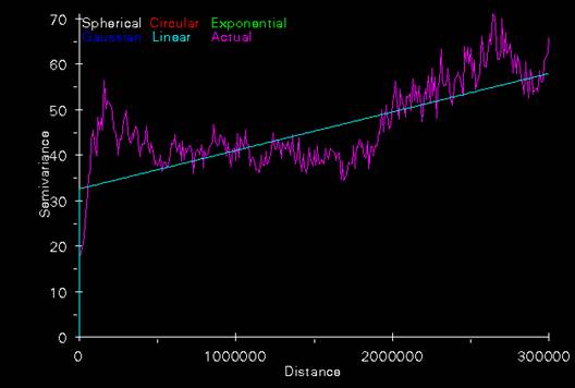
We chose to fit a linear model to this data. The nugget was estimated ab about 33.
By putting ‘Spherical, Gaussian, Exponential’, etc. into the kriging command instead of ‘Linear’ Arc/INFO would have calculated a different function to characterize the autocorrelation.
Questions
for Task #2:
1) Read the three grids (idwozone, krigozone, and varozone) and a co-registered state boundary coverage into ArcView. Compare and contrast the appearance of these three grids.
2) Where are the areas of high ‘ozone’ concentration in idwozone and krigozone? Do the two images agree in general?
3)
What is the IDW and Kriged estimate of o3apr2oct_ at the
Task
#3: Spatial interpolation with a known full valid coverage to validate estimates
against
In this task you will be IDWing and Kriging interpolated grids from data you already have ‘truth’ for. To do this you will artificially blind yourself by getting elevation, population density, and landcover information at only the usozonesites points and then interpolating them. To do this you will need to do a ‘summarize zones’ command with ArcView using usozonesites and each of the following three grids: nademlza, uspopden, and naigbplza. This will generate several tables which you will have to read into excel, delete most columns, (keep ‘Monitor’ and ‘Median’), change name of median to elevation, popden, and landcover as appropriate, and join these three tables back to usozonesites.pat. Now you are ready for spatial interpolation.
The Elevation dataset
Get an IDW and a Kriged interpolated grid from the usozonesites pointcoverage from grid
Grid: idwelevation=IDW(usozonesites,
elevation,. #, 2,
Sample, 11, 1000000, 10000)
Grid: krigelevation = kriging(usozonesites, elevation,. #, both, varelevation,
linear, sample, 11, 1000000, 10000)
Questions
1) Look at these interpolated fields. How well did IDW or Kriging spatially interpolate elevation?
2) Does the varelevation grid seem honest with respect to characterizing the error of estimate?
3) Create two error grids with simple map algebra, from grid the commands would be:
Grid: idweleverror = nademlza – idwelevation
Grid: krigerror = nademlza – krigelevation
Display the grids idweleverror and krigeleverror in ArcView using standard deviation as a classification and color scheme. How similar are the error patterns?
4) Now create the absolute error (so over and underestimates do not cancel each other out when you calculate the mean). To do this use the absolute value function in grid:
Absidweleverror = abs(idweleverror)
Abskrigeleverror = abs(krigeleverror)
Which interpolator had the lowest Mean Absolute Deviation?
5) Comment on the usefulness of IDW and Kriging for interpolating Elevation data with point coverages of the density of usozonesites.
The Population Density Dataset
Using the population density
dataset for the conterminous
Questions 1-B thru 5-B same as elevation dataset
The Landcover Dataset
Using the landcover dataset
naigbplza dataset for the conterminous
Note: smart students will not
do this and explain to me that it is an inappropriate exercise.
6) Print the variograms for
elevation and population density on a sheet of paper side by side. How do they
compare and how can they be interpreted in light of what you know about the
spatial variability of population and elevation in the conterminous
Task #4: De-Trended Kriging of
Ozone in Rocky
Space is not the cause of
variability in measurements of elevation, ozone concentration, etc. Kriging,
IDW, and other spatial interpolaters merely take advantage of the fact that
spatial auto-correlation exists. It is even better to build a model using
spatially explicit measure of dependent variables, apply them to extensive
spatial coverages, look at the errors at known points
and only krig the errors. Approaches like this are sometimes called
‘de-trended’ kriging. For example, let’s consider ozone concentration in
Compare this to a simple ‘kriging’ and simple ‘IDWing’ of the original point data.
Procedures:
Produce a simple kriged estimate of ozone:
Grid:
smpkriggsmnp = kriging(ozonelocs, adj_intsv_, # ,
both, varsmpkrig, linear, sample, 5, 500000, 200)
Produce a simple IDW estimate of ozone:
Grid:
smpkriggsmnp = IDW(ozonelocs, adj_intsv_, #, 2, Sample, 5, 500000, 10000)
Now you need to gather the data needed to build a model that uses more than simply the spatial relationships of the ozone measurements at the ozone monitoring sites. To do this you need to read in the ozonelocs point coverage, and the following grids: gsmnpelev, gsmnp_slope, gsmnp_landcover. Do the GIS manipulations necessary to get a table with the following fields and appropriate values in the records: Code4_site, Elevation, Adj_intsv_, gsmnpelev, gsmnp_slope, gsmnp_landcover. Read that table into JMP. How does the Elevation variable correlate with the gsmnpelev variable? This should be a strong relationship. It’s not perfect because the elevation measurements were made with different devices. Now build a univariate or multivariate model that predicts Adj_intsv_ using the other variables. Build a grid of that model estimate with ArcView or Arc/INFO’s Grid module.
Questions:
1) How do these models compare visually?
2) How could you quantitatively compare the accuracy of these interpolations?
-for extra credit, brownie points, and my undying admiration…. Fire up the new Arc GIS 8.1 and see if you can figure out how to get the Geo-Statistical analyst extension to do cross-validation.
LAST EXERCISE:
Use JMP to generate 3 random variables. 300 records with the following fields:
X coordinate 100*random
Uniform Y Coord 100*random Uniform Z value
Create shapefile of points convert to point coverage. Krig these points and attach print-out of variogram and interpret.